During 1999-2001 while working as a senior manufacturing and process engineer, Gary E. Kilpatrick, PE, DFE designed a special belt conveyor for an existing industrial pre-notch roll forming process. Gary’s new belt conveyor would replace an existing belt conveyor that was problematic. The pre-notch roll forming process produced a slotted “U” shaped channel called “Strut’ which was used during construction projects to hang electrical conduit, piping and lighting systems into the ceiling of buildings.
This roll forming process was made up of the following operations: (1) a free-standing sheet metal roll stand that vertically supported a 7 inch wide roll of 14 gage galvanized sheet metal weighing approximately 6,500 pounds; (2) The sheet metal was unwound and pulled from the parent roll and (3) entered a stress reversal sheet metal straightener to remove the curve from the sheet metal material as it was being stored on the parent roll; (4)The sheet metal was then pulled through a 75 ton Minster kinetic energy punch press with a special advancing mechanism external to the punch press. The punch press used a special die set and punched six slots into the centerline of the sheet metal material with each cycle of the press ram; (5) The sheet metal material was then pulled through by a Yoder roll former which formed the galvanized sheet metal material into the “U” shaped strut channel; (6) The strut channel was then pushed through a Yoder flying shear that would cut the strut channel into predetermined lengths; (7) Each piece of strut was then removed from the conveyor by one or more employees who stacked each strut channel onto special racks staged below the belt conveyor sitting on gravity roller conveyors; (8) Once a rack was full of strut channels, the employee would push the rack underneath the belt conveyor where gravity would pull the rack into the warehouse for storage.
The existing problematic conveyor was 60 feet long and was designed like a roadway truss bridge made from welded 18 gauge aluminum square tubing. The conveyor structure was designed in two halves and was bolted together at its mid-section. The conveyor was supported at each end by legs bolted or welded to the bottom of the conveyor truss structure. The conveyor would sag at its bolted mid-section causing problems with the racking below. From time to time during setup operations and during a strut product run, a strut channel would exit the roll former or flying shear and veer off at an angle striking the aluminum conveyor truss bending or breaking the aluminum truss elements. Over time, the aluminum conveyor deteriorated more and more to the point where maintenance was forced to patched up this conveyor just to keep the operation running.
Gary approached the company planet manager to discuss this issue. He was asked to request quotes from various design firms that could design and build a new conveyor. The quotes came back too expensive ranging from $25,000 to $50,000 with an estimated delivery time in weeks to months. So Gary met with the company maintenance department and asked the manager if his employees had the equipment and resources to build a 60 foot belt conveyor and the answer was yes. The maintenance department was very excited about a project like this and was looking forward to the challenge. So Gary discussed this with the planet manager and told him that he could design a conveyor in-house much cheaper and the in-house maintenance department could build it much quicker. So the planet manager asked Gary to create a design concept and a bill of material with cost and an estimated time of installation. So Gary determined that he could build the conveyor in-house for around $6,500.00 and the maintenance department could build and install it within 4 to 6 weeks. So the planet manager gave Gary the green light to move forward with the project.
Gary’s belt conveyor design criteria was as follows: (1) it could not sag anywhere along its length; (2) the conveyor frame had to be tough to take the abuse from the strut channels and roll former during setup and operation; (3) the conveyor frame and belt height had to be adjustable to fine tune its placement at the exist of the flying shear; (4) the employees asked that the new conveyor incorporate a kick-off mechanism to assist them in safely removing the strut channels from the conveyor belt.
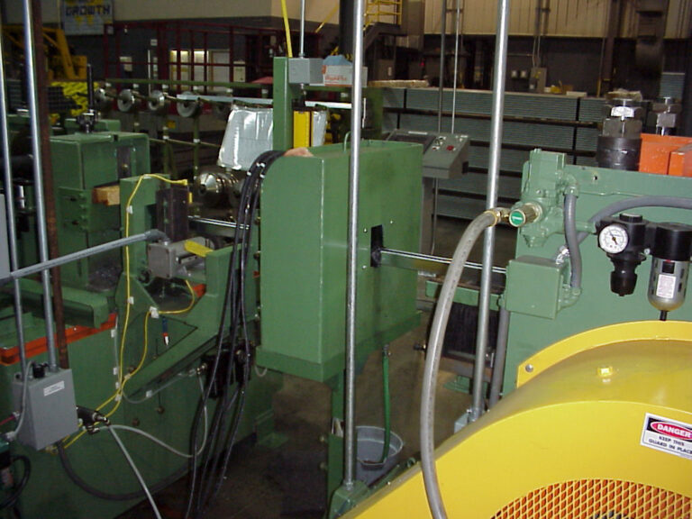
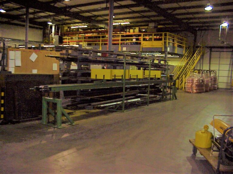
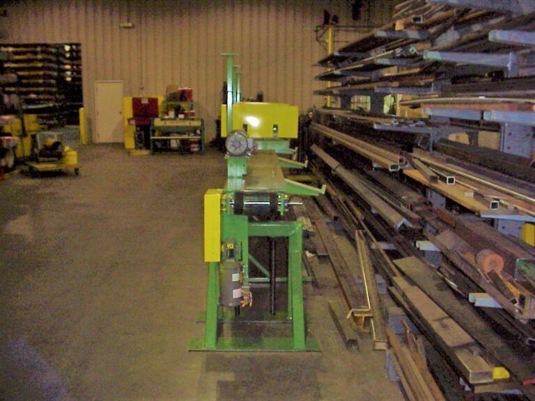
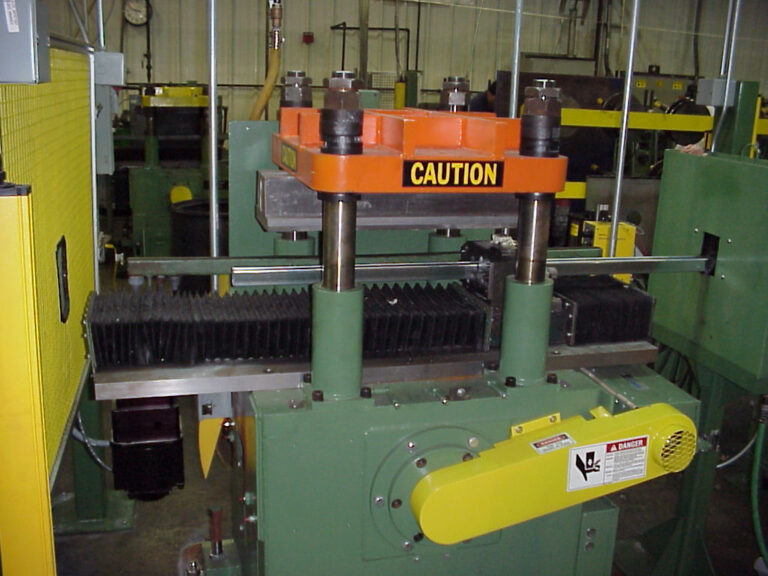
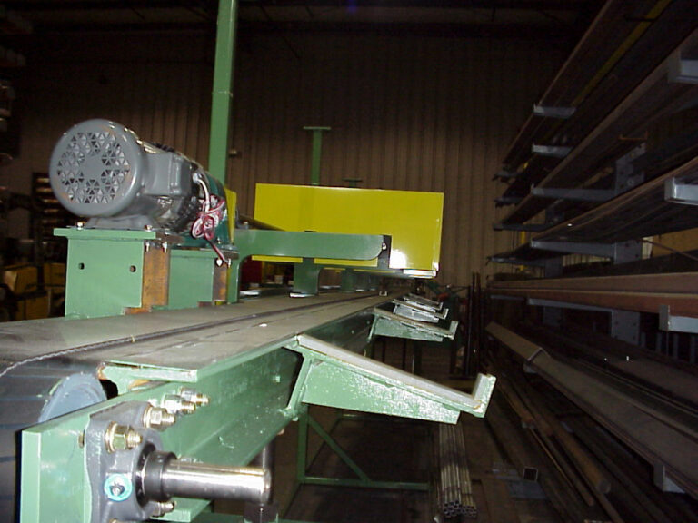
Gary designed the conveyor using two standard wide flange W 6 x 20 I beams positioned horizontally and adjacent to each other which created the frame of the conveyor as well as a cavity for the belt to loop underneath and return. The design utilizing the I-beams would immediately satisfy design requirements (1) and (2) above. Gary designed the conveyor belt bed from a long piece of 7 inch wide galvanized sheet metal that was tack welded to the I-beams, de-burred and curled down on each end so as not to snag the conveyor belt. The bed surface was polished to reduce drag. Gary designed the conveyor with a series of gravity conveyor rollers installed between the inside of the two I-beams to act belt return rollers as the belt moved off the end of the conveyor bed. Gary designed two leg stands that were adjustable using jack screws and where bolted to the bottom of the I-Beams. Gary designed a guarded kick-off mechanism for the employees that was powered by an electric motor and gear reducer. Every pinch point on the conveyor was guarded per OSHA regulations and ANSI standards. The conveyor can be seen in the pictures below.
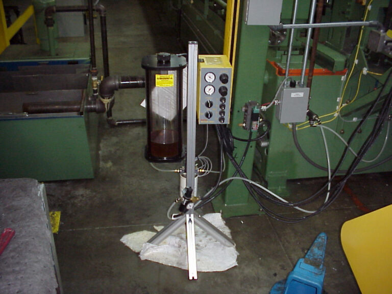
During this conveyor project, Gary purchased and had installed a new Yoder flying shear. He also designed, had built in-house and had installed a strut spraying system to apply a rust preventative (RP) to protect the new strut channels while they sat waiting for distribution to customers.
After approximately 20 years, these conveyors are still in service today because of their rugged design.