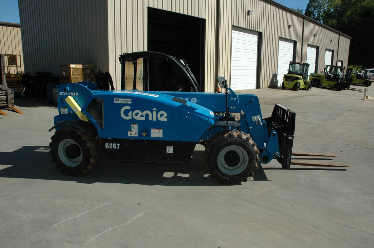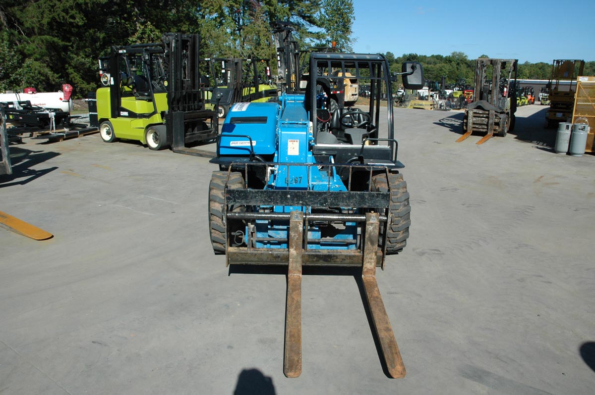
Gary E. Kilpatrick, PE, DFE is one of the leading telehandler experts in the United States. The telehandler was invented by Joseph Cyril Bamford (JCB) and was released for sale to industry during 1977. The machine was marketed as the 520 Telescopic Handler also referred to as the Loadall. JCB designed the telehandler for two markets (1) construction and (2) agriculture. The machines designed for construction could incorporate a pair of stabilizers mounted forward of the front axle as an option to the customer. The JCB telehandler was designed with a boom tip “Q Mount” where various boom tip attachments can be quickly switched out to change the function of the machine. Some of these attachments are (a) the carriage and forks so the machine could be operated as a forklift, (b) a grapple so the machine could be operated to pick up debris, (c) a jib with a hook so the machine could be operated as a small lifting crane, (d) an open ended shovel so the machine could be used as a frontend loader, (e) a snow blower attachment and (f) sweeper. Other attachments are available.
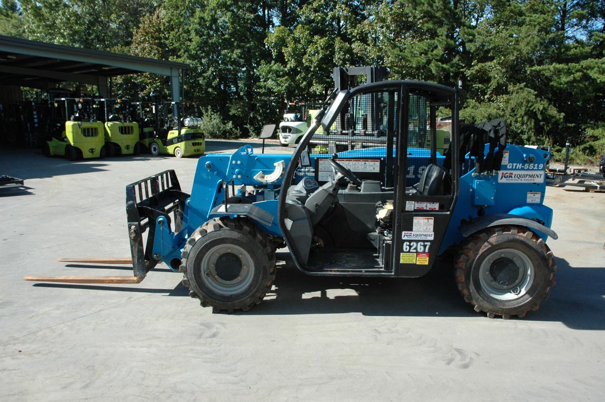
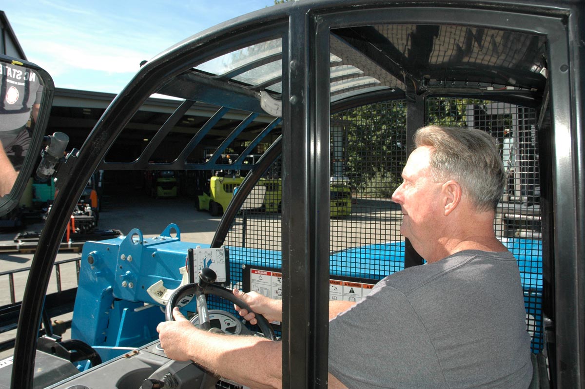
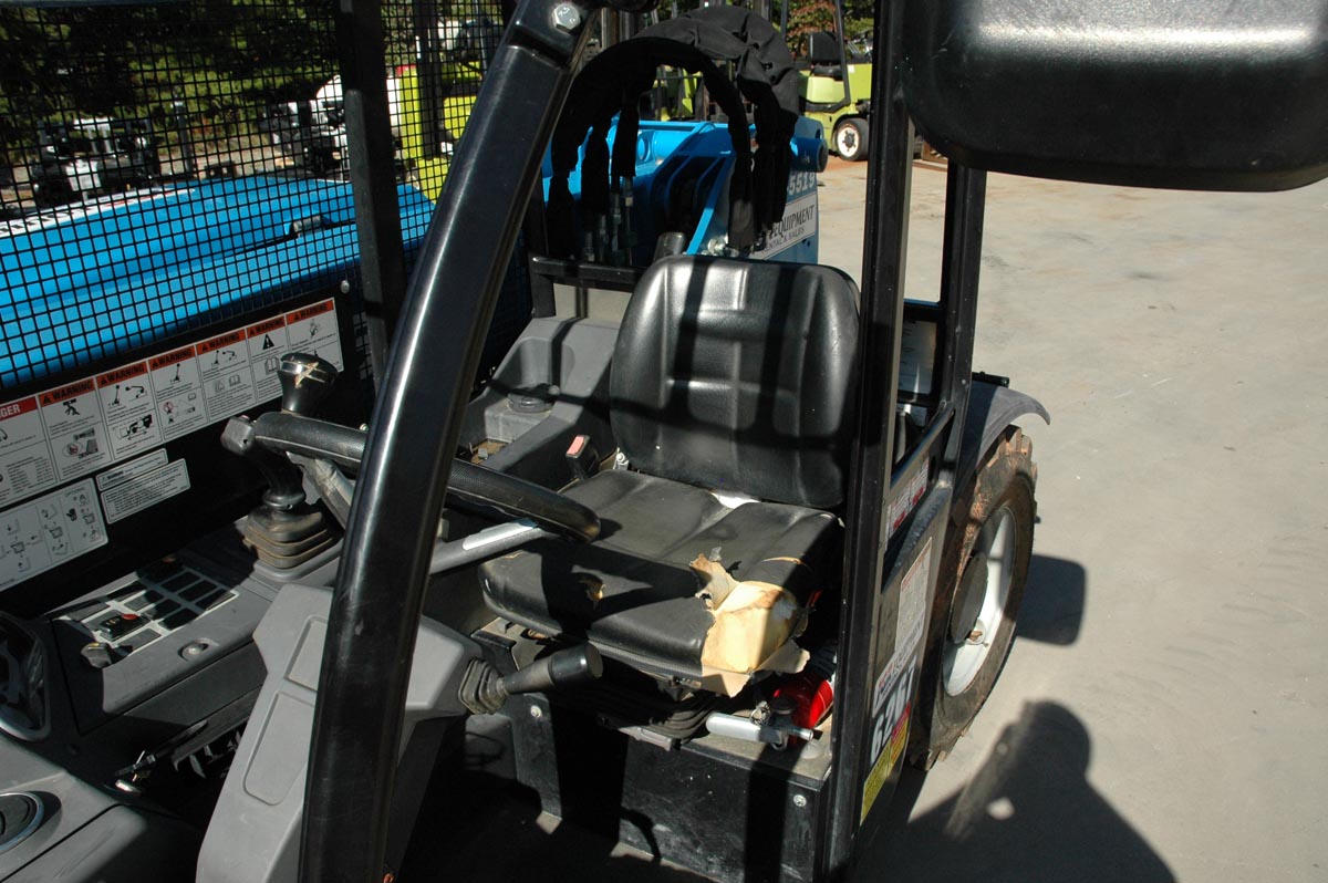
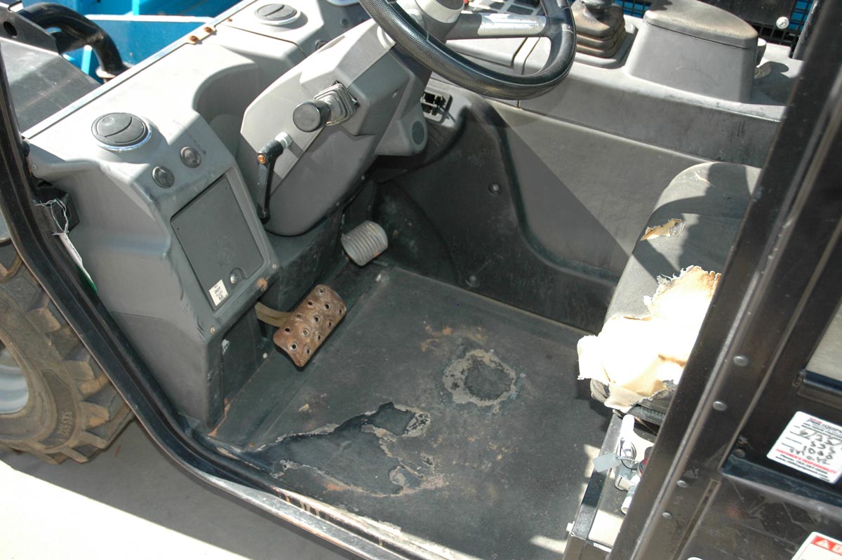
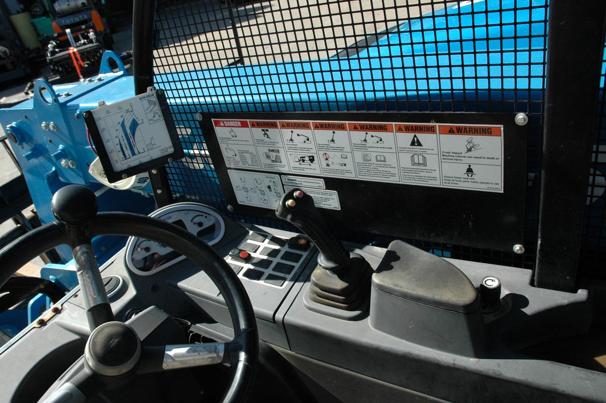
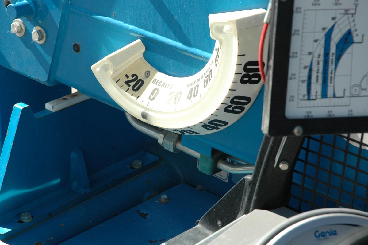
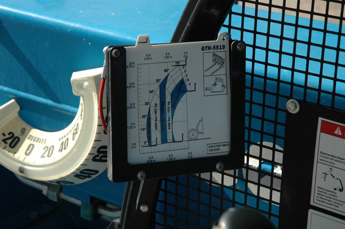
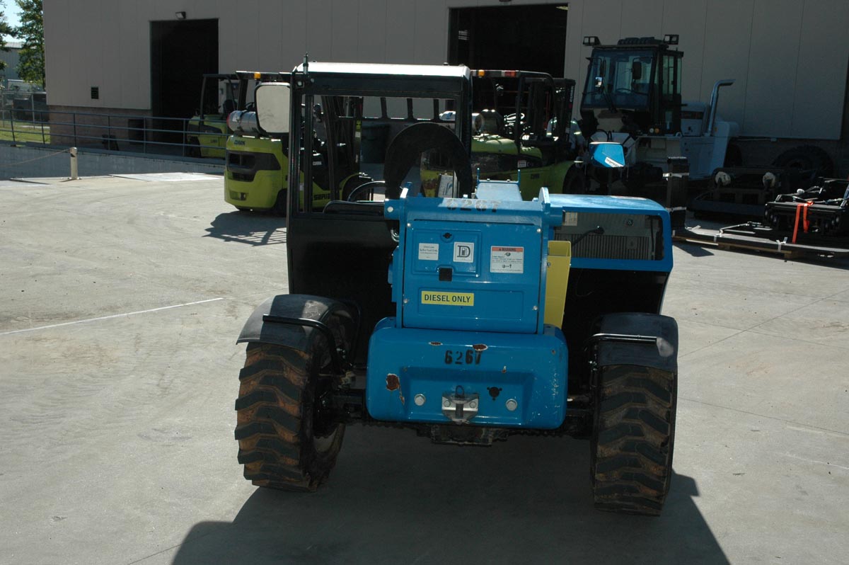
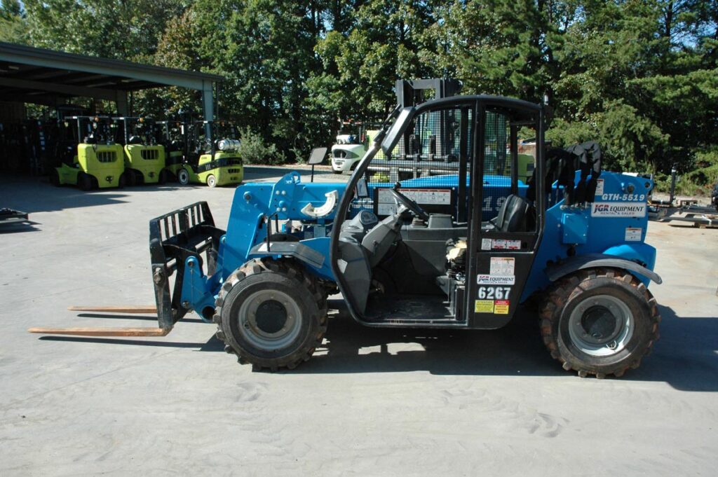
A telehandler is a much different machine than a forklift. The telehandler like a mobile crane has a telescoping boom that can be adjusted by operator controls to telescope (lengthen) the boom outward. Like a mobile crane, the boom is marked on the side adjacent to the operator’s cab with lettered labels to indicate to the operator how far out in length the operator has telescoped the boom. Like a mobile crane, the telehandler boom can also be luffed (rotated upward) to various angles. Telehandler models are available that have a rotating superstructure mounted to the lower carrier on a slew ring and pinion. Like a mobile crane, the superstructure incorporates by design the cab and boom (referred to as a swing cab) and the operator can “slew” (rotate) the superstructure, its cab and boom horizontally around in a circle. Like a mobile crane, this model of telehandler incorporates two sets of outriggers located two in the front and two in the rear. Because of the boom telescoping length adjustment capability and its boom luffing and slewing capability, the telehandler operates like a mobile crane and has mobile crane operational attributes and mobile crane safety devices. These are namely (1) a boom angle indicator, (2) a frame level indicator, (3) has a series of plastic or laminated paper load charts to aid the operator in determining the machine’s net lifting capacity depending on the geometry of the boom tip (telescoped boom length, boom luff and slew angles) and the attachment mounted on the boom tip, (4) construction telehandlers can be fitted with frontend stabilizers as an option to the customer, (5) the telehandler incorporates a frame angle leveling cylinder so the operator can level the machine laterally before a lift, (6) a Load Moment Indicator (LMI) and (7) a trained spotter hand signals chart, (8) operator’s manual and AEM rough terrain forklift safety manual that must be read by the operator. Like a mobile crane, the load charts are assigned to the telehandler by model, serial number or VIN. Other than the operator, safety and service manuals, the load charts are the most important documents that a trained and certified telehandler operator must have access to in the cab while operating the machine. These load charts are printed in color and must always be stored inside of the telehandler’s cab in the factory installed easy to access sealed box usually mounted on the back of the seat so the documents are not damaged, soaked with water and are kept clean. The telehandler has a special holding frame attached to the dashboard to hold and support a load chart for the operator to refer to. Like a mobile crane, the telehandler’s telescoping boom has a series of lettered labels indicating how long the boom has been extended outward by the operator. Using the load chart, the operator must use the boom length and the boom angle within the load chart before the telehandler is used to lift a payload. The operator should use two pointers such as a pen or pencil so he or she can chart the machine’s net lifting capacity to determine how much load weight the telehandler can lift with a particular boom tip orientation. In addition to the paper or plastic load charts, the newer telehandlers may have a dashboard electronic display that, upon starting the machine’s engine, may default to the load chart screen based on the attachment installed on the boom tip, or the operator may have to toggle through the dashboard electronic display to locate the correct load chart. This may depend on the customer options the machine was ordered with. The electronic load chart will display a small bubble or circle that moves inside of the electronic chart graph lines as the telehandler’s boom is lengthened, shortened, luffed or slewed which shows the operator the telehandler’s net lifting capacity based on the geometry of the boom tip.
Gary offers his expertise as a mechanical design engineer in telehandler design, operations, maintenance and telehandler safety to his legal and insurance clients throughout the United States. Gary always maintains an active telehandler operator’s certification and is certified to train others on how to safely operate telehandler and certified these individuals.